Tutorial 02 Planning
1. Description
This tutorial will teach how to use ROSPlan to call a planner and produce plans.

2. Prior Setup
This tutorial assumes that ROSPlan is already installed, following the instructions on the gihtub README: https://github.com/KCL-Planning/ROSPlan.
Also that you have already followed Tutorial 01: Problem Generation, as this tutorial will extend the launch file created there.
3.1 Launching the Planner Interface
Change directory to the ROSPlan workspace.
Copy the launch file tutorial_01.launch from the previous tutorial to create tutorial_02.launch, and then paste the following lines under the problem generation </include>:
	<!-- planner interface -->
	<include file="$(find rosplan_planning_system)/launch/includes/planner_interface.launch">
		<arg name="use_problem_topic"    value="true" />
		<arg name="problem_topic"        value="/rosplan_problem_interface/problem_instance" />
		<arg name="planner_topic"        value="planner_output" />
		<arg name="domain_path"          value="$(arg domain_path)" />
		<arg name="problem_path"         value="$(find rosplan_demos)/common/problem.pddl" />
		<arg name="data_path"            value="$(find rosplan_demos)/common/" />
		<arg name="planner_command"      value="timeout 10 $(find rosplan_planning_system)/common/bin/popf DOMAIN PROBLEM" />
	</include>
The Planner Interface node, once launched, will provide a service that will call a PDDL planner and then publish the plan that it generates on a new topic.
The node is launched from the included launch file. In that file you can see the type of node which is launched (popf_planner_interface)
<node name="$(arg node_name)" pkg="rosplan_planning_system" type="popf_planner_interface" respawn="false" output="screen">
There are a number of possible node types that can be launched as a Planner Interface, depending upon the planner that you wich to use. Some of them are:
fd_planner_interfaceff_planner_interfacelpg_planner_interfacemetricff_planner_interfacepopf_planner_interfacesmt_planner_interfacetfd_planner_interface
3.2 The Launch File Explained
		<arg name="use_problem_topic"    value="true" />
		<arg name="problem_topic"        value="/rosplan_problem_interface/problem_instance" />
The use_problem_topic parameter, set true, means that the problem passed to the planner will be the one last published on the problem topic. This links our Planer Interface to a specific Problem Interface node.
<arg name="planner_command" value="timeout 10 $(find rosplan_planning_system)/common/bin/popf DOMAIN PROBLEM" />
The planner command is the command line that will be executed to call the planner. It contains two special strings, DOMAIN and PROBLEM that will be replaced with the domain and problem paths respectively.
3.3 Launching
From the terminal, launch the file:
roslaunch tutorial_02.launch
You should see that the Planner Interface has started:
KCL: (/rosplan_planner_interface) Ready to receive
To view the nodes, open a second terminal and launch rqt, and select the Plugins -> Introspection -> Node Graph plugin:
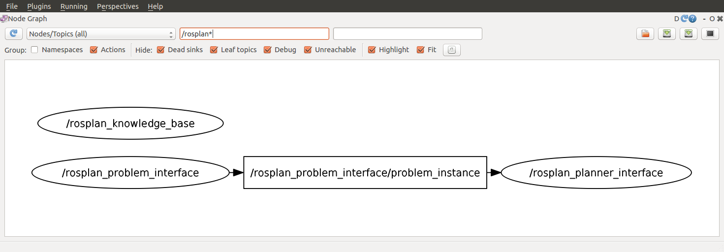
3.3 Calling the Planner
In the second terminal, first call the problem generation service (using tab complete is helpful), and then call the planning service:
rosservice call /rosplan_problem_interface/problem_generation_server
There will be no output in the second terminal, but in the first terminal you should see the following lines:
KCL: (/rosplan_problem_interface) (problem.pddl) Generating problem file.
KCL: (/rosplan_problem_interface) (problem.pddl) The problem was generated.
KCL: (/rosplan_planner_interface) Problem recieved.
This means that the Planner Interface is correctly subscribed to the problem topic of the Problem Interface. It has received the problem, which you can display using rostopic echo.
Now, call the planing service to generate a plan:
rosservice call /rosplan_planner_interface/planning_server
Again, there will be no output in the second terminal, but in the first terminal you will see the output produced by the Planner Interface:
KCL: (/rosplan_planner_interface) (problem.pddl) Writing problem to file.
KCL: (/rosplan_planner_interface) (problem.pddl) Running: timeout 10 ./src/rosplan/rosplan_planning_system/common/bin/popf [...]/domain_turtlebot.pddl [...]/problem.pddl > [...]/plan.pddl
KCL: (/rosplan_planner_interface) (problem.pddl) Planning complete
KCL: (/rosplan_planner_interface) (problem.pddl) Plan was solved.
The plan has been written to a file plan.pddl, the path to which you can see in the output. You can also view the plan by echoing the topic:
rostopic echo /rosplan_planner_interface/planner_output -p
The Planner Interface publishes a plan like this:
  0.000: (undock kenny wp1)             [10.000]
 10.001: (localise kenny)               [60.000]
 70.002: (goto_waypoint kenny wp0 wp0)  [60.000]
130.003: (goto_waypoint kenny wp0 wp1)  [60.000]
190.004: (goto_waypoint kenny wp1 wp2)  [60.000]
250.005: (goto_waypoint kenny wp2 wp3)  [60.000]
310.006: (goto_waypoint kenny wp3 wp4)  [60.000]
3.4 Writing a Script to call both Services
Rather than calling each service by hand, we’ll create a simple script to use ROSPlan to generate a problem and then a plan. Create a new file called tutorial.bash and paste the following lines inside:
rosservice call /rosplan_problem_interface/problem_generation_server
rosservice call /rosplan_planner_interface/planning_server
Give permission for the script to be executed and run it with the following commands:
chmod 755 tutorial.bash
./tutorial.bash
For information on how to call ROS services from code, take a look at the tutorials for c++ and python.
4. What’s Next?
Simple Plan Execution in the next tutorial: Tutorial 03: Plan Execution