Tutorial 05 Plan Execution II
1. Description
This tutorial will describe the Esterel Plan representation and show how to view the plan currently under execution.
2. Prior Setup
This tutorial assumes that you have have already followed Tutorial 04: Planning, and will use the same launch files and scripts.
3.1 Launch File
Change directory to the ROSPlan workspace.
Copy the launch file from Tutorial 04 as tutorial_05.launch, and add the action_duration parameter to each of the simulated actions so that the simulated actions look like the following:
	<!-- sim actions -->
	<include file="$(find rosplan_planning_system)/launch/includes/simulated_action.launch" >
		<arg name="pddl_action_name" value="undock" />
		<arg name="action_duration" value="5" />
	</include>
	<include file="$(find rosplan_planning_system)/launch/includes/simulated_action.launch" >
		<arg name="pddl_action_name" value="dock" />
		<arg name="action_duration" value="15" />
	</include>
	<include file="$(find rosplan_planning_system)/launch/includes/simulated_action.launch" >
		<arg name="pddl_action_name" value="localise" />
		<arg name="action_duration" value="60" />
	</include>
	<include file="$(find rosplan_planning_system)/launch/includes/simulated_action.launch" >
		<arg name="pddl_action_name" value="goto_waypoint" />
		<arg name="action_duration" value="45" />
	</include>
Then take another look at the interfaced_planning_system.launch in the rosplan_planning_system package.
You can open the file using:
rosed rosplan_planning_system interfaced_planning_system.launch
	<!-- plan parsing -->
	<include file="$(find rosplan_planning_system)/launch/includes/parsing_interface.launch">
		<arg name="knowledge_base"   value="rosplan_knowledge_base" />
		<arg name="planner_topic"    value="/rosplan_planner_interface/planner_output" />
		<arg name="plan_topic"       value="complete_plan" />
	</include>

	<!-- plan dispatch -->
	<include file="$(find rosplan_planning_system)/launch/includes/dispatch_interface.launch">
		<arg name="knowledge_base"           value="rosplan_knowledge_base" />
		<arg name="plan_topic"               value="/rosplan_parsing_interface/complete_plan" />
		<arg name="action_dispatch_topic"    value="action_dispatch" />
		<arg name="action_feedback_topic"    value="action_feedback" />
	</include>
The two files included here launch the Parsing Interface and Plan Dispatch nodes. The nodes launched by those included files are not the same Simple PDDL variants used in Tutorial 03: Plan Execution I. Instead, they launch nodes of type: pddl_esterel_plan_parser and pddl_esterel_plan_dispatcher.
3.2 Launching
From the terminal, launch the file:
roslaunch tutorial_05.launch
Switch to a second terminal and source the workspace. Using the script written for Tutorial 04: Simulated Actions, start problem generation, planning, and plan dispatch.
./tutorial.bash
This time, the plan will be dispatching in the time specified by the parameters in the simulated actions instead of taking it from the plan.
3.3 Viewing the Esterel Plan
Open a third terminal, and source the workspace. From this terminal, take a look at the information for the dispatcher node:
rosnode info /rosplan_plan_dispatcher
Have a look at the publishers and subscribers for this node. Note that the message type for the complete_plan topic is different from the simple plan. Use rosmsg show rosplan_dispatch_msgs/EsterelPlan to see the structure of the new plan message:
rosplan_dispatch_msgs/EsterelPlanNode[] nodes
  byte ACTION_START=0
  byte ACTION_END=1
  byte PLAN_START=2
  byte node_type
  int32 node_id
  string name
  rosplan_dispatch_msgs/ActionDispatch action
    int32 action_id
    string name
    diagnostic_msgs/KeyValue[] parameters
      string key
      string value
    float32 duration
    float32 dispatch_time
  int32[] edges_out
  int32[] edges_in
rosplan_dispatch_msgs/EsterelPlanEdge[] edges
  int32 edge_id
  string edge_name
  int32 signal_type
  int32[] source_ids
  int32[] sink_ids
  float64 duration_lower_bound
  float64 duration_upper_bound
This plan representation is an array of nodes, which can be of type: plan start, action start, or action end; and an array of edges between nodes, each associated with upper and lower temporal bounds.
Use this command,
rostopic echo /rosplan_parsing_interface/complete_plan -n 1
to show the plan message that was passed to the dispatcher:
  -
    node_type: 2
    node_id: 0
    name: plan_start
    action:
      action_id: 0
      name: ''
      parameters: []
      duration: 0.0
      dispatch_time: 0.0
    edges_out: [0, 2, 5, 9, 14, 19, 24, 29]
    edges_in: []
  -
    node_type: 0
    node_id: 1
    name: undock_start
    action:
      action_id: 0
      name: undock
      parameters:
        -
          key: v
          value: kenny
        -
          key: wp
          value: wp0
      duration: 10.0
      dispatch_time: 0.0
    edges_out: [1]
    edges_in: [0]
The plan begins with a node representing the plan start. The next node corresponds to the start of the first action in the plan, (undock kenny wp0).
There is a lot of text describing the plan, and it is not easy to see the structure. Instead, there is a graphical representation. Using rosnode info again, notice that the pddl_esterel_plan_dispatcher is publishing on a topic /rosplan_plan_dispatcher/plan_graph. Use rostopic echo to view the contents of this topic:
rostopic echo /rosplan_plan_dispatcher/plan_graph -n 1 -p
The contents of the message is a DOT graph, visualising the plan.
digraph plan {
0[ label="plan_start",style=filled,fillcolor=black,fontcolor=white];
1[ label="undock_start",style=filled,fillcolor=darkolivegreen,fontcolor=white];
2[ label="undock_end",style=filled,fillcolor=darkolivegreen,fontcolor=white];
3[ label="localise_start",style=filled,fillcolor=darkolivegreen,fontcolor=white];
4[ label="localise_end",style=filled,fillcolor=darkolivegreen,fontcolor=white];
5[ label="goto_waypoint_start",style=filled,fillcolor=darkolivegreen,fontcolor=white];
6[ label="goto_waypoint_end",style=filled,fillcolor=darkolivegreen,fontcolor=white];
7[ label="goto_waypoint_start",style=filled,fillcolor=darkolivegreen,fontcolor=white];
8[ label="goto_waypoint_end",style=filled,fillcolor=darkolivegreen,fontcolor=white];
9[ label="goto_waypoint_start",style=filled,fillcolor=darkolivegreen,fontcolor=white];
10[ label="goto_waypoint_end",style=filled,fillcolor=darkolivegreen,fontcolor=white];
11[ label="goto_waypoint_start",style=filled,fillcolor=darkolivegreen,fontcolor=white];
12[ label="goto_waypoint_end",style=filled,fillcolor=darkolivegreen,fontcolor=white];
13[ label="goto_waypoint_start",style=filled,fillcolor=darkolivegreen,fontcolor=white];
14[ label="goto_waypoint_end",style=filled,fillcolor=darkolivegreen,fontcolor=white];
"0" -> "1" [ label="[0, inf]" , penwidth=2 , color="red"]
"1" -> "2" [ label="[10, 10]" , penwidth=2 , color="black"]
"0" -> "2" [ label="[0, inf]" , penwidth=2 , color="red"]
"2" -> "3" [ label="[0, inf]" , penwidth=2 , color="black"]
"3" -> "4" [ label="[60, 60]" , penwidth=2 , color="black"]
"0" -> "4" [ label="[0, inf]" , penwidth=2 , color="red"]
"4" -> "5" [ label="[0, inf]" , penwidth=2 , color="black"]
"2" -> "5" [ label="[0, inf]" , penwidth=2 , color="black"]
"5" -> "6" [ label="[60, 60]" , penwidth=2 , color="black"]
"0" -> "6" [ label="[0, inf]" , penwidth=2 , color="red"]
"6" -> "7" [ label="[0, inf]" , penwidth=2 , color="black"]
"4" -> "7" [ label="[0, inf]" , penwidth=2 , color="black"]
"2" -> "7" [ label="[0, inf]" , penwidth=2 , color="black"]
"7" -> "8" [ label="[60, 60]" , penwidth=2 , color="black"]
"0" -> "8" [ label="[0, inf]" , penwidth=2 , color="red"]
"8" -> "9" [ label="[0, inf]" , penwidth=2 , color="black"]
"4" -> "9" [ label="[0, inf]" , penwidth=2 , color="black"]
"2" -> "9" [ label="[0, inf]" , penwidth=2 , color="black"]
"9" -> "10" [ label="[60, 60]" , penwidth=2 , color="black"]
"0" -> "10" [ label="[0, inf]" , penwidth=2 , color="red"]
"10" -> "11" [ label="[0, inf]" , penwidth=2 , color="black"]
"4" -> "11" [ label="[0, inf]" , penwidth=2 , color="black"]
"2" -> "11" [ label="[0, inf]" , penwidth=2 , color="black"]
"11" -> "12" [ label="[60, 60]" , penwidth=2 , color="black"]
"0" -> "12" [ label="[0, inf]" , penwidth=2 , color="red"]
"12" -> "13" [ label="[0, inf]" , penwidth=2 , color="black"]
"4" -> "13" [ label="[0, inf]" , penwidth=2 , color="black"]
"2" -> "13" [ label="[0, inf]" , penwidth=2 , color="black"]
"13" -> "14" [ label="[60, 60]" , penwidth=2 , color="black"]
"0" -> "14" [ label="[0, inf]" , penwidth=2 , color="red"]
}
Create a new file in the current directory, plan.dot and copy in the contents of the message. If you copy from the terminal, make sure to remove the “data:” prefix at the start of the message.
Use dot (install it if you do not have it) to convert the plan into a PDF:
dot -Tpdf plan.dot > plan.pdf
Open the PDF to view the plan. The node and edge colours change depending upon the state of execution.
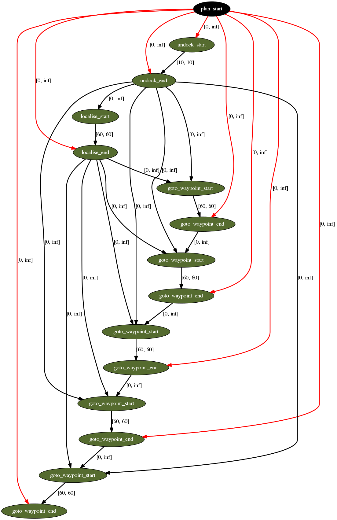
Edges represent temporal constraints, actions supporting preconditions, and mutual exclusion relations. Note that the nodes representing the ends of the undock and localise actions support all of the goto_waypoint action starts. This is because the goto_waypoint action has the condition:
	:condition (and
		(at start (localised ?v))
		(over all (undocked ?v))
		...
4. What’s Next?
In the next tutorial, Tutorial 06: Knowledge Base I, we will explore the services provided by the ROSPlan Knowledge Base node.
In Tutorial 10: Action Interface we describe how to write a real action interface, to replace the simulated actions, and connect the PDDL action with the real lower-level control.